Tuesday, October 18, 2016
Mobile 'Störsender' von Audi
Ich wohne unweit einer vielbefahrenen Straße.
Nun ist mir folgendes in meinen "benachbarten WLAN" aufgefallen:

Dabei handelt es sich anscheinend um WLAN Netze die in Audi KfZ on-board erzeugt werden.
Die konkrete Konfiguration führt leider dazu das umgebende Netze beeinträchtigt werden da sowohl die Wahl des Kanals (6) als auch die Wahl der Kanalbreite (40 Mhz) ungeschickt/ignorant ist.
Ich nehme an das Kanal 6 und 40Mhz die Werkseinstellungen sind.
Zur Bandbreite: 802.11-2012 fordert das Systeme beim Erkennen von überlappenden Netzen von 40 auf 20 Mhz zurückschalten. Eine normgerechte Implementation lässt sich nicht auf 40Mhz festlegen.
Im städtischen Umfeld findet man daher auch kaum 40Mhz breite 2.4Ghz Netze, von ein paar bekloppten Plasteroutern mal abgesehen.
Die Beobachtung das alle Audi MMI Wlans die an meinem Netz vorbeikommen 40Mhz breit sind lässt mich schliessen das Audi hier die entsprechenden Mechanismen nicht implementiert hat und somit diverse Standards,u.a. 802.11-2012 nicht entspricht. Dies kann übrigens auch die Zulassung der Geräte betreffen.
Das alles wäre mir fast egal, wäre das 2,4Ghz ISM Band nicht so schmal.
Mit 20Mhz existieren maximal 3 überlappungsfrei Kanäle (1,6,11 bzw 1,7,13). Überlappungsfrei ist da auch relativ da die Filter nicht immer die entsprechende Flankensteilheit besitzen. Wenn die Fahrzeuge 20Mhz breit auf Kanal 6 wären, so bliebe ungefähr 2/3 des Spektrums unbehelligt.
Sie sind aber 40Mhz breit und auf Kanal 6, was so ziemlich die schlechteste Lösung ist.
Es gibt 2 überlappungsfreie 40Mhz Bereiche (1+5 und 9+13).
40Mhz auf Kanal 6 heisst das kein überlappungsfreier Kanal exisitiert - auch keine 20Mhz Kanäle. :-(
Daimler kriegt das übrigens korrekt hin ;-)
Daher die Bitte an Audi:
Seit doch gute Nachbarn und verhaltet euch normgerecht (20 Mhz Kanalbreite).
Nun ist mir folgendes in meinen "benachbarten WLAN" aufgefallen:

Dabei handelt es sich anscheinend um WLAN Netze die in Audi KfZ on-board erzeugt werden.
Die konkrete Konfiguration führt leider dazu das umgebende Netze beeinträchtigt werden da sowohl die Wahl des Kanals (6) als auch die Wahl der Kanalbreite (40 Mhz) ungeschickt/ignorant ist.
Ich nehme an das Kanal 6 und 40Mhz die Werkseinstellungen sind.
Zur Bandbreite: 802.11-2012 fordert das Systeme beim Erkennen von überlappenden Netzen von 40 auf 20 Mhz zurückschalten. Eine normgerechte Implementation lässt sich nicht auf 40Mhz festlegen.
Im städtischen Umfeld findet man daher auch kaum 40Mhz breite 2.4Ghz Netze, von ein paar bekloppten Plasteroutern mal abgesehen.
Die Beobachtung das alle Audi MMI Wlans die an meinem Netz vorbeikommen 40Mhz breit sind lässt mich schliessen das Audi hier die entsprechenden Mechanismen nicht implementiert hat und somit diverse Standards,u.a. 802.11-2012 nicht entspricht. Dies kann übrigens auch die Zulassung der Geräte betreffen.
Das alles wäre mir fast egal, wäre das 2,4Ghz ISM Band nicht so schmal.
Mit 20Mhz existieren maximal 3 überlappungsfrei Kanäle (1,6,11 bzw 1,7,13). Überlappungsfrei ist da auch relativ da die Filter nicht immer die entsprechende Flankensteilheit besitzen. Wenn die Fahrzeuge 20Mhz breit auf Kanal 6 wären, so bliebe ungefähr 2/3 des Spektrums unbehelligt.
Sie sind aber 40Mhz breit und auf Kanal 6, was so ziemlich die schlechteste Lösung ist.
Es gibt 2 überlappungsfreie 40Mhz Bereiche (1+5 und 9+13).
40Mhz auf Kanal 6 heisst das kein überlappungsfreier Kanal exisitiert - auch keine 20Mhz Kanäle. :-(
Daimler kriegt das übrigens korrekt hin ;-)
Seit doch gute Nachbarn und verhaltet euch normgerecht (20 Mhz Kanalbreite).
Saturday, September 10, 2016
Making Of wiekaltistderkanal.de Sensor Version II
I am building a new sensor for wiekaltistderkanal.de.
In June 2016 I wrote: "Münster's local bathing lake for the masses is the local canal, "Dortmund-Ems Kanal". Excellent water quality & very popular. Looking for a project that fills a void - @todendah suggested: "I want to know whether it's too cold!". So that became our first [FreifunkLP] project deployed in the wild. Starting today we have deployed a solar powered temperature sensor at Stadthafen 2. We are really curious how long it will last. :-) The sensor is autonomous (solar) and very close to water so we are not yet convinced that it will last. The river police however speculated that it will get nicked first. :-)"
The coppers were right: It got stolen after 2 months. So I am building a new one.
I have been asked a few details about the sensor, so I am documenting the build here.
Some references: Dortmund Ems Kanal: Wikipedia (german, dutch)
The first version: https://www.thethingsnetwork.org/forum/t/time-for-a-swim/2567/4

To no surprise, water is the enemy. The sensor was (and will be) mounted about 30cm above water level at Dortmund-Ems Kanal. The water level there is very stable (the authorities monitor, publish (yay!) the water levels. So I thought that (besides rain) there would be the occasional splash.
Boy was I wrong! The canal is a waterway with (relative to it's size) rather large ships (110m x 10m) which cause significant swell. So significant that the sensor is fully submerged on a regular basis. V1 was not made for that. It had a few flaws:
Flaw #1: Antenna
For whatever reason I used an external rod antenna screwed onto a gold SMA connector. I knew the antenna was not weather proof but I thought that it would probably take much longer than the sensors lifetime for the thing to rot. That was correct. ;-) What I did not think is that water will run down the inside of the antenna and end up in the inside of the SMA connection and make it's way to the inside. Someone from warpzone asked (innocently) why I was using an external antenna with a plastic case. Duh! So at first revision I removed the antenna, plugged the hole and used an internal wire antenna instead.
Flaw #2: Ventilation opening
I think that any case need some sort of ventilation to avoid condensation. My first solution for this was an opening in the bottom containing a very small pipe that extended a few cm up into the case. I thought this would provide minimal ventilation and be immune to the occasional splash. Furthermore the pipe was small enough that it would keep out most insects. I never found out whether this anti-condensation approach worked since at each revision I found about 1cm of water in the case.
The pipe was later extended to got all the way to the top of the case.
Flaw #3: Power production/consumption
V1 used a 70x55mm 0,5W panel which provided plenty of power during sunny days. But even in summer this was insufficient at overcast days. On problem is that the panel is not ideally oriented. The panel is glued to the case to make the while setup as robust as possible. Nothing I want to change here. V1 used a Couloumb counter to measure battery charge/discharge. Rob65 in the TTN forum pointed out that it has a major design flaw as it drains energy through an ill dimensioned pull-up resistor. I payed for this flaw with 1mA. :-(

When using a 3,3V system you also need to close the two solder jumpers (SJ2, SJ3) on the underside.
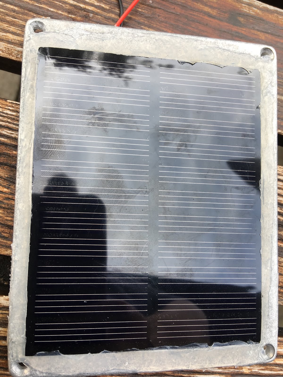
For the solar panel, I removed the wires from the panel, drilled two holes in the case and glued the whole panel to the case and finally re-soldered the wires. I also filled the holes from the inside with silicone which helps to prevent the wires to come loose when moved around. After the silicon has somewhat cured I used more of the stuff to seal edges on the front. The protective film the panel is removed as last step.
I am really sure that this is watertight. However since the panel I've used has "open" (unsealed) edges I think it's possible that moisture may creep in from the front. Time will tell.
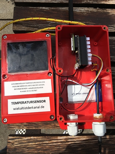
In the end I had something like this:


Required battery capacity assumption:
V1 consumed about 1,1mA
V2 should have much lower power consumption, approx 1mA lower.
If we assume it's 1mA (its going to be lower) we'd need 24mAh per day.
In wintertime (below -20℃ is a very rare event) - the capacity will roughly half, so 48mAh per day.
LiPos do somewhat between 200 and 500 cycles. This is a problem. This should (be able to last) longer than a year. This page suggest that limiting depth discharge increases lifetime a lot.
x10 = 500mAh.
The end of the world is near, for sure, but until then there will be some light during the day.
What I don't know how much energy the panel will produce on a cloudy winter day. Data from V1 suggested that on rainy (summer) days there may not be any charge at all.
Anyway, for good measure I'll go with ~2000mAh.
I also want to do an experiment with supercaps, perhaps with the next build


The process of adding the solar panel is described above.
Furthermore, I drilled a hole in the top to mount the antenna.
There are two holes in the bottom, one for the sensor wires and one for a "breathing plug". This is basically a small piece of goretex membrane and is IP68 proof. (Product, search for "vent plug membrane" to find more)


By the way, if someone has a suggestion how to integrate a waterproof USB connector - to be able to do maintenance without breaking the seal - that would be welcome information
As you can see I went for chains instead of cable ties this time :-)
I changed the OTA protocol a bit to give higher resolution values for temperatures and to cope with the additional sensors. Furthermore the Autonomo has a voltage divider hooked to Vbat and an AD input that allows for simple measurements of the battery voltage which I also included.
The Node-RED sketch was reworked accordingly.

The current software can be found here: https://github.com/kgbvax/kanaltemp
In June 2016 I wrote: "Münster's local bathing lake for the masses is the local canal, "Dortmund-Ems Kanal". Excellent water quality & very popular. Looking for a project that fills a void - @todendah suggested: "I want to know whether it's too cold!". So that became our first [FreifunkLP] project deployed in the wild. Starting today we have deployed a solar powered temperature sensor at Stadthafen 2. We are really curious how long it will last. :-) The sensor is autonomous (solar) and very close to water so we are not yet convinced that it will last. The river police however speculated that it will get nicked first. :-)"
The coppers were right: It got stolen after 2 months. So I am building a new one.
I have been asked a few details about the sensor, so I am documenting the build here.
Some references: Dortmund Ems Kanal: Wikipedia (german, dutch)
The first version: https://www.thethingsnetwork.org/forum/t/time-for-a-swim/2567/4
Lessons learned from Version 1
To no surprise, water is the enemy. The sensor was (and will be) mounted about 30cm above water level at Dortmund-Ems Kanal. The water level there is very stable (the authorities monitor, publish (yay!) the water levels. So I thought that (besides rain) there would be the occasional splash.
Boy was I wrong! The canal is a waterway with (relative to it's size) rather large ships (110m x 10m) which cause significant swell. So significant that the sensor is fully submerged on a regular basis. V1 was not made for that. It had a few flaws:
Flaw #1: Antenna
For whatever reason I used an external rod antenna screwed onto a gold SMA connector. I knew the antenna was not weather proof but I thought that it would probably take much longer than the sensors lifetime for the thing to rot. That was correct. ;-) What I did not think is that water will run down the inside of the antenna and end up in the inside of the SMA connection and make it's way to the inside. Someone from warpzone asked (innocently) why I was using an external antenna with a plastic case. Duh! So at first revision I removed the antenna, plugged the hole and used an internal wire antenna instead.
Flaw #2: Ventilation opening
I think that any case need some sort of ventilation to avoid condensation. My first solution for this was an opening in the bottom containing a very small pipe that extended a few cm up into the case. I thought this would provide minimal ventilation and be immune to the occasional splash. Furthermore the pipe was small enough that it would keep out most insects. I never found out whether this anti-condensation approach worked since at each revision I found about 1cm of water in the case.
The pipe was later extended to got all the way to the top of the case.
Flaw #3: Power production/consumption
V1 used a 70x55mm 0,5W panel which provided plenty of power during sunny days. But even in summer this was insufficient at overcast days. On problem is that the panel is not ideally oriented. The panel is glued to the case to make the while setup as robust as possible. Nothing I want to change here. V1 used a Couloumb counter to measure battery charge/discharge. Rob65 in the TTN forum pointed out that it has a major design flaw as it drains energy through an ill dimensioned pull-up resistor. I payed for this flaw with 1mA. :-(
Features for version II
I had plans for a new version even before the original sensor got nicked.
Goals:
- Long term autonomy (ideally through winter)
- Improved water resistance
- Two temperature sensors to measure temperatures at two depths
- Improved idiot resistance
- Against damage
- Against theft
Parts
- Case: Aluminium HPDC case (Reichelt RND 455-00042). This is not waterproof by design but I believe some silicone will do the job. Maintenance is difficult though.
- Antenna: Delock LTE Antenna 88749. Since it's a metal case, I need an external antenna again. Perhaps there are smaller ones out there but that's the one I got. This is rugged and made for outdoor (so they say). I did not worry too much about RF performance as this will close to a gateway (it should be at the level of a stubby).
- Energy:
- 1W solar panel 80x100 (seeed studio). This fits nicely on the case and should provide more power than V1 to carry us through the long dark winter. ;-) Although I currently believe that 0,5W would do as well.
- Battery: I went with a 2000mAh single cell lipo. See the discussion on "Battery" below.
- Sensors
- 3x DS18b20
- LTC4150 Coulomb counter (Sparkfun, meh)
- MCU: SODAQ Autonomo. This is an expensive part. I considered using a Feather instead but then I went with the same part as V1 as I have code & experience to do power management on that part (which I may need to re-discover for other platforms). I also used the groove shield (which is absolutely not required) but makes it a bit modular and I had it lying around anyway. You could use other parts of course, for example a RN2483 with a Teensy LC (you need to add LiPo charging then) or an Adafruit Feather LoRa.
- LoRaWAN: RN2483 on bee socket.
Power
As the goal is to create something that is 100% solar powered & autonomous for a long time and I have little experience with such a thing I decided in V1 (and V2) that I want to measure charge/discharge to better understand what's going on. This is done with a coulomb counter (instead of a fuel gauge).
Wiring:

If you do not remove that R7, you will see 1mA loss through ill-dimensioned 3k3 pull-up.
I used a microscope to unsolder this but and magnifying glass should do.
I used a microscope to unsolder this but and magnifying glass should do.

When using a 3,3V system you also need to close the two solder jumpers (SJ2, SJ3) on the underside.
For the solar panel, I removed the wires from the panel, drilled two holes in the case and glued the whole panel to the case and finally re-soldered the wires. I also filled the holes from the inside with silicone which helps to prevent the wires to come loose when moved around. After the silicon has somewhat cured I used more of the stuff to seal edges on the front. The protective film the panel is removed as last step.
I am really sure that this is watertight. However since the panel I've used has "open" (unsealed) edges I think it's possible that moisture may creep in from the front. Time will tell.
In the end I had something like this:


Battery
V1 used a 1600mAh lipo which was plenty.Required battery capacity assumption:
V1 consumed about 1,1mA
V2 should have much lower power consumption, approx 1mA lower.
If we assume it's 1mA (its going to be lower) we'd need 24mAh per day.
In wintertime (below -20℃ is a very rare event) - the capacity will roughly half, so 48mAh per day.
LiPos do somewhat between 200 and 500 cycles. This is a problem. This should (be able to last) longer than a year. This page suggest that limiting depth discharge increases lifetime a lot.
x10 = 500mAh.
The end of the world is near, for sure, but until then there will be some light during the day.
What I don't know how much energy the panel will produce on a cloudy winter day. Data from V1 suggested that on rainy (summer) days there may not be any charge at all.
Anyway, for good measure I'll go with ~2000mAh.
I also want to do an experiment with supercaps, perhaps with the next build
Temperature Sensors
These are DS18B20 Dallas One-Wire sensors. You can get them in a watertight enclosure with (long) wiring. I am using two to get two reading at different depths. The 2nd sensor will be 1m below the first one. Although one-wire sensors can be daisy chained (forming a bus) I am too lazy for the and use two DIOs. This will be using powered (3-wire) mode.
Sensor 1
Black (GND) - to- GND
Red (Pwr) - to - 3V3
Yellow (data) - to - DIO2
Sensor 2
Like sensor 1 but data goes to DIO3
Between data lines and 3V3 I use a 5,6k pull-up. Wiring for this is "flying" ;-) Heat-shrink tubes hold this together...


I also used hot-glue filled heat-shrink tubes to tie the two cables together at some points and coloured heat shrink tubes spaced at 10cm around the anticipated water-line. These depth markers will help with installation later on.
Since I had spare material I rigged a third sensor to record the battery temperature / inside temperature of the case.
Since I had spare material I rigged a third sensor to record the battery temperature / inside temperature of the case.
MCU
The Autonomo comes ready to go. I've disabled on-board charge indicator LED (SJ4 - http://support.sodaq.com/sodaq-one/autonomо/features-autonomo/) since nobody will see it ;-)Case
The case is aluminium so "the elements" should not be a a problem. It will develop a (gray) oxide film which is waterproof thus preventing further corrosion. (There are scenarios where this does not work, by the way). It's not watertight by design but since there is a single cover I plan to use by beloved silicone to make it watertight.The process of adding the solar panel is described above.
Furthermore, I drilled a hole in the top to mount the antenna.
There are two holes in the bottom, one for the sensor wires and one for a "breathing plug". This is basically a small piece of goretex membrane and is IP68 proof. (Product, search for "vent plug membrane" to find more)


By the way, if someone has a suggestion how to integrate a waterproof USB connector - to be able to do maintenance without breaking the seal - that would be welcome information
As you can see I went for chains instead of cable ties this time :-)

warpzone.ms tribute feature
None :-(
Software
The Node-RED sketch was reworked accordingly.

The current software can be found here: https://github.com/kgbvax/kanaltemp
TODO
* Sealing the case
* Mounting
* Adapt the feeds for ELK, opensensemap and dweet.
Subscribe to:
Posts (Atom)